FOR BLENDER 2.92+
USER MANUAL for using KIT OPS PARALLAX
©2021 Altuit, Inc, All Rights reserved
Documentation written by Chipp Walters and Michael Semprevivo
V1.0
To Install KIT OPS PARALLAX
| Note: KIT OPS PARALLAX works best with KIT OPS 3 PRO, but you can also use KIT OPS FREE. Using KIT OPS 3 PRO allows you to easily save your KIT OPS PARALLAX objects.
Download the latest version of KIT OPS PARALLAX KIT OPS PARALLAX works with Blender 4.0+.
To Install the KIT OPS PARALLAX addon: Drag/drop the zip file in the 3D Viewport. Please see http://cw1.me/kitopsdocs for information on installing KIT OPS and the KPACKS.
VIDEOS
Introductory Video:
Tutorial Video:
What is it? {#what-is-it?}
KIT OPS PARALLAX is a systemized approach for creating virtual rooms using only one plane which are able to be viewed from different angles in real-time as if in real 3D. It works with Blender 2.92+. It is recommended to also use KIT OPS 2 PRO to save the material and plane efficiently so that it may be easily deployed on any object later using the KIT OPS asset management system.
Who is it for? {#who-is-it-for?}
KIT OPS PARALLAX is targeted at customers who want to create their own KIT OPS PARALLAX room objects as KIT OPS INSERTS to other scenes… They work great in large scale 3D architectural scenes, both current and future. KIT OPS PARALLAX rooms created with KIT OPS PARALLAX can be resold as well.
HOW does it work? {#how-does-it-work?}
At its most basic level KIT OPS PARALLAX is a simple plane and a Blender material applied that when added to a scene magically displays an optical illusion showing a 3D room inside that plane. And when you rotate the plane or the camera, you can see inside the room that is being displayed.
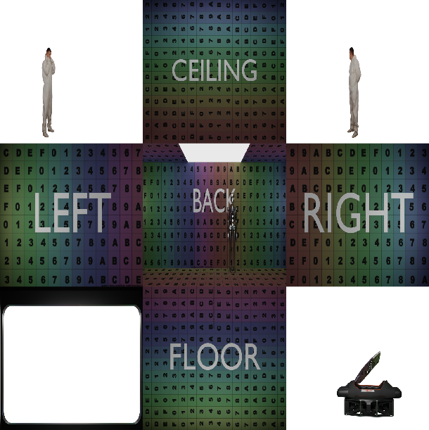
The material is a special collection of node groups that provides you the ability to adjust different parts of the effect. It uses only one 3,000 by 3, 000 image map which we call a cross map. If you look at the cross map you will see that the room is divided into regions as displayed below.
 |
|---|
The corners of the cross map represent the sprite layers in the final material. Sprite 1 is at the top left Sprite 2 the top right Sprite 3 the bottom right and Sprite Front is the bottom left. All sprites can be adjusted in the material with the exception of the sprite front which always stays on the front of the room and it is used for things like curtains or shades or decals on the front of a window. In this case it’s cutting a radiused window opening into the room.
Overview of the workflow
KIT OPS PARALLAX is structured in a wizard-like workflow. You work through each step and you can go back and forth between steps. Once completed you are rewarded with a final single plane parallax object which you can then use KIT OPS 2 PRO to create an INSERT so that you can apply it in any scene with just a press of a button.
Getting Started
Below are the steps broken down for you in an easy to understand way so that you can easily work through the process of creating your parallax object.
The Interface
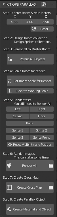 |
The KIT OPS PARALLAX product includes both the object with the material as well as an add-on that helps you create the KIT OPS PARALLAX object. The creation of a KIT OPS PARALLAX room is straightforward and the add-on guides you through the process step by step. |
|---|
When you launch Blender with the new add-on, you are immediately asked to load the scene template and after you press the button the scene is loaded for you.
NEWER VERSIONS OF BLENDER don’t automatically select the scene. After loading the scene be sure to select Parallax Model: 
The template consists of a room design that works especially well with KIT OPS PARALLAX. The first thing you’re going to want to do is save a copy of your scene because the template file is write only and you cannot save over top of it
Step 1: Room Size
Next, change the dimensions of the room to create the size of the room you want to create. Please note the room dimensions are in metric and must stay in metric. Do not try and enter inches or feet in those fields, you’ll have to convert them someplace else.
Step 2: Design
The next thing you’ll do is design the room and there are a few things you need to be paying attention to when you design the room. There are five specific zones that are used in creating the room.
These zones are the left wall, the right wall, the back wall, the ceiling, and the floor. If you notice, there are two basic cubic regions in your scene, the front area and the back area. The front area is where you will create the images in the cross map for the left, right, floor, and ceiling. The back area is where you will create the scene for the back image.
When dealing with the front area you can add elements, but it is important to keep them close to the same plane as the walls or ceilings or floor. Any change in perceived depth of items on those areas will not be reflected as 3D but will only be reflected in a 2D map so you’re best off just texturing the surfaces or adding very thin objects like a picture frame or a wall lighting sconce.
Tip: as a general rule. It’s better for your patterns to go in the X and Z direction and not in the Y direction. This way they won’t conflict with any of the geometry on the back room.
Tip: it’s always a good idea to use a dark surface for the floor. The reason for this is that the sprite layers do not generate shadows and so a light floor with sprites on top of it will not look as real as a dark one.
The back area should have the floor different from the front area so that you will not see a striking band of light and dark difference between the two in the final KIT OPS PARALLAX cross map material. Again use a dark floor. You can cut holes in the back and have things go further back. You can even move the back wall deeper in the wide dimension if you want. There’s a lot of experimentation that can be done with the back area. The most important consideration for design on the back is to not have any sort of patterns going in the Y direction. Again, use patterns in the Z and the X direction but never in the Y direction.
Sprites
Sprites are very important to add realism and depth to your room. A room without sprites just does not look right so do not forget to add them to your scene.
Sprites can be any sort of objects like tables or chairs or room dividers but keep in mind that as you position them you want them to have their depth value be less than their width value In other words the y dimension will be the lesser of the two dimensions. They can be as tall as you like.
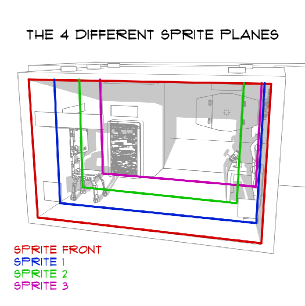
You can add up to four different Sprite layers to your cross map and final material. See the image below to better understand the zones and where to position each layer.
 |
|---|
 |
Make sure and place your sprites close together in the Y direction so they will all be similarly rendered as zones on the same plane.
Tip: It’s probably not a good idea to use people as sprites because if you animate the room they will be static and not moving and probably be somewhat confusing as a realistic device.
Collections
There are five collections that you’re going to want to be paying particular attention to in the scene file. They are: ROOM, Sprite 1, Sprite 2, Sprite 3, Sprite Front.
For the add-on to properly create the images needed for the cross map, all the objects in your scenes must belong to one of the five collections.
Anything on the left or right walls or the floor or the ceiling should be in the room collection. Anything on the back area should also be in the room collection.
Each set of objects inside the room that will be used as sprites, should be placed in the appropriate sprite zone collection. Traditionally, Sprite 1 is somewhere about 25 to 35% inside the room Sprite 2 is between 35% and 65% Sprite 3 is between 65% and all the way to the back of the room. All items on the front of the room would belong in the Sprite front collection.
Important: you cannot have any collections or collection instances inside any of these five collections. If you do, KIT OPS PARALLAX will automatically show an error and tell you to either 1) remove the collection or; 2) convert the instance to a mesh. With regard to 1) collections, it’s easy to just select the collection and delete it in the outliner. The objects will not be deleted. With regard to 2), you can convert your collection instance to a mesh by using the Objects > Apply > Make Instances Real menu command.
Also, make sure that if you have any parented objects in any of the collections, that the parent object is either a mesh or a curve. It can not be an empty.
Step 3: Parent Objects
Once all of the objects have been placed in the proper collections, you can then parent them to the master room and this is done by just clicking a single button.
Step 4: Scale Room for Render
Then, in order to create the cross map renders, everything will need to be scaled properly so that it will fit into the different camera views. Press the Set Room Scale for Render button and this is automatically done for you.
Next examine your scene and see if there are any objects that are left out of the now shrunken room, and if so, go back to the regular working scale by pressing the Back to Working Scale button and move them into the correct collection and then parent it again by using the parent button. Then press the Set Room Scale for Render button and see if everything looks good.
You can always use the Back to Working Scale button if you want to edit your room.
Step 5: Render tests
You may want to check individual renders which you can do by pressing specific render buttons. Please note that when rendering a sprite layer the whole room object will move in order to get the best image of the sprite layer and you can use the reposition button to put it back but it’s not really that necessary because anything you do afterwards will automatically put it back as well.
It’s a good idea to at least test one of the Sprite layers to make sure that you’re not rendering something you don’t want to.
Step 6: Render All
When satisfied, click the little folder icon next to the render all button and it will open up the folder where your final renders will be deployed. This is a temporary folder which will be deleted when you close Blender. If you like, you can also open up the console to see the render progress which may be handy if you are expecting a long render time .
*You can also use K-CyclesX of you want to. It will speed up the renders dramatically.
Keep in mind that KIT OPS PARALLAX requires that Cycles be used to render the cross map and it will not work if you try to use it with EEVEE rendering. It should automatically be set for you by the template.
Pressing the Render All button will begin the render process and KIT OPS PARALLAX will render nine separate square 1,000 by 1,000 images. You can see the progress in the folder and on the terminal console. The button will stay blue until it is complete.
Step 7: Create Cross Map
Once finished, then press the Create Cross Map button, and automatically all nine images are composited into one 3,000 by 3, 000 pixel cross map. You can examine the cross map in the folder that is already open.
Step 8: Create Parallax Object
Finally, press the Create Parallax Object button to create your material and it will take you to a different scene called Parallax Material and there you can fine tune your KIT OPS PARALLAX material. Use the Return to Model Scene button to go back to the original scene if you need to make changes.
The KIT OPS PARALLAX material
There are a number of different controls that you have with regard to the KIT OPS PARALLAX material. You may want to fine tune the positioning of the sprites in your final material. You can do this by adjusting the X,Y and Z offsets in each of the Sprite fields. You can also adjust the color and the brightness and color tone for your final object as well. And lastly, there is an adjustment to tweak how much of a fringe is being shown around the transparent part of your sprites. It should be set correctly but you might want to adjust if you’re seeing a little white halo around any of your sprites.
Exporting to KIT OPS
If you have Kit OPS 2 Pro installed, you can now save your KIT OPS PARALLAX object with the included material as a Kit OPS INSERT. Everything is already set up for you and all you need to do is open up KIT OPS and press create INSERT. And then you save the INSERT wherever you want, and create a thumbnail the way you want and then close factory mode and you will be back in your scene file.
Remember, when you create an INSERT, KIT OPS will automatically save the scene that you’re working on before going into factory mode.
One thing to note is that KIT OPS PARALLAX automatically creates new material names each and every time it creates material and this is so that there are no material conflicts inside of Blender. It also changes the node name for the cross map image as well because that can also be a source of conflict.
KIT OPS PARALLAX Techniques and Tips
Don’t use any Y-axis lines in the back room area. They will destroy the perspective illusion of the back area.
You can have the sides of the front go in/out a little bit as long as the ones closest to the “window” are out the most.
Keep a dark floor so that people won’t see the lack of shadows.
Use floor to ceiling sprites to create more depth in your room.
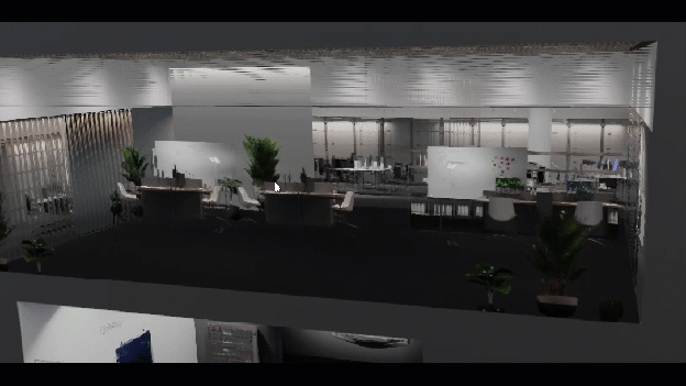
Make the floor in the back room reflective and the reflections will look correct. But, if you make the floor in the front room reflective they will not look correct.
Don’t forget, you can always edit your cross map in Photoshop, or my favorite, Affinity Photo. You Can change the color tone and even add in other decals and curtains and blinds for the front sprite.
If one of the sprites or images for the cross map doesn’t look correct, you can render it individually and then just save it to the temp folder where the others are and then rebuild your cross map.
Consider scaling your sprites in the Y dimension so that they are very thin. This Will make them match the floor perspective a lot better. Don’t forget we’re only rendering from the front view for each sprite.
Troubleshooting
Help
If you’re having issues, please first try http://cw1.me/troubleshoot. You can always ask questions at http://cw1.me/discord
Sometimes after I save an INSERT, I go back to my model scene and things are out of scale.
The solution is simple, just File > Revert and you should be good to go. We’re not exactly sure why this happens as closing Factory mode essentially does a revert as well.
Why do my sprites show the entire scene?
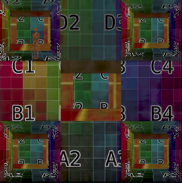 |
In the case of an image like this one, where the sprites do not have any transparency, the probable reason is you’ve reset the scene rendering to EEVEE. In order to render with proper transparency, be sure and use Cycles. |
|---|